Goodman Gas Furnace: GMS9/GCS9
Re: Flashing Code 4
(Assuming original control board)
Code 4 = Limit Circuit Open
If the Limit Circuit opens, the burners will be de-energized and the air circulation and vent blower will be turned on until the Limit Circuit closes. The diagnostic light code for this is four short flashes followed by a pause.
► The diagnostic code will go away once the Limit Circuit closes (not a Hard Lockout).
| Qty |
Possible Causes: |
| 1 |
Bad Blower Motor / Capacitor |
|
Dirty Air Filter |
|
Bad Control Board |
|
Clogged Evaporator Coil |
|
Under-sized Ductwork |
|
High Gas Pressure |
|
Bad Limit |
|
Blower Speed too Low |
CHECKOUT:
1. Check Blower Operation
- When the furnace is Flashing Code 4, the indoor blower and inducer motor should be running.
- Ensure that the blower motor is operating and airflow is coming from the registers.
2. Check Control Board
- If the furnace is still in a Code 4 lockout, the blower should be operating, so move on to the Voltage Check.
- If the Code 4 goes away, activate either a call for Heat W or Fan G to get the blower to Power On.
- Voltage Check
- Check for 120V between CIR-N and HEAT.
- Power Present + Blower Operates → Step 3. Check Limits
- Power Present + No Blower Operation = Bad Blower Motor or Capacitor
- No Power ⇒ Check for power between CIR-N and COOL.
- Still No Power = Bad Control Board
3. Check Limits
- There are (2) limits in the Limit Circuit that will generate a Code 4: (1) Auto-Reset Limit in the furnace heat exchanger and (1) Manual-Reset Limit (In the Blower Deck on Upflow, or On the Blower Housing on Counterflow).
- Check the Limit Circuit
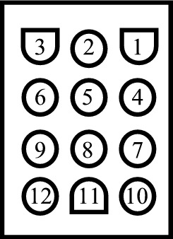
- Check for 24V between "C" and Pin #1 (Pink) of the 12-pin plug on the circuit board.
- Check for 24V between "C" and Pin #7 (Blue) of the 12-pin plug on the circuit board.
- Power on Both Pins = Limit Circuit Closed
- Limit Circuit Closed + Code 4 = Bad Control Board
- Power on One Pin Only = Limit Circuit Open
- Check for 24V between "C" and both sides of each limit to determine which is Open.
4. Check Temperature Rise
- Start the furnace with a call for heat.
- Check and record the return air temperature near the furnace (at the filter if possible) with the blower on.
- Check the supply air temperature (in a straight duct run near the furnace) as the furnace operates.
- Compare the actual temperature rise to the rated temperature rise on the furnace nameplate. (typically 40 - 70 deg.)
5. Check Air Filter
- Remove air filter and recheck temperature rise.
6. Check Gas Pressure
- De-energize the call for heat and allow the furnace to cool.
- Turn off power to the furnace and close the gas safety shut-off.
- Hook-up a gas pressure gauge to the manifold (leaving) test port on the gas valve.
- Open the gas safety shut-off valve and re-apply furnace power.
- Activate a call for heat and monitor the manifold gas pressure when the gas valve opens.
- Natural Gas = 2.5" w.c. minimum to 3.5" w.c. maximum
- LP Gas = 9" w.c. minimum to 11" w.c. maximum
7. Check Blower Speed
- Check the blower motor speed wire attached to the "Heat" output of the control board.
- Red = Low
- Yellow = Med Low
- Blue = Med Hi
- Black = Hi
- If possible, increase the Heat blower speed and Re-Check Temperature Rise
8. Check Duct Static Pressure
- Check the return static pressure (in the blower door if possible).
- Check the supply static pressure (between the furnace and evaporator coil if possible).
- High Duct Static = Above 0.5" w.c.
- High Return Static + Low Supply Static = Restricted Return Ductwork
- Low Return Static + High Supply Static = Clogged Coil or Restricted Supply Ductwork
- Compare static on both sides of evaporator coil.
- High Static Entering Coil + Low Static Leaving Coil = Clogged Coil
- Low Return Static + Low Supply Static = Dirty Blower Wheel or Dirty Recoup Coil
